 English
 русский
 Español
No. 200 Gaoxin RD, Shanghua St, Lanxi, Zhejiang, P. R China
The Multiple Specifications Rack Pinion Gear is a versatile mechanical...
See DetailsThe stepped rack pinion gear is a specialized variant in gear systems characterized by multiple discrete sections with varying tooth heights or profiles, designed to accommodate different load or speed requirements along the rack length. Achieving a high precision level in these gears is critical to ensure smooth engagement, accurate motion transfer, and minimal backlash.
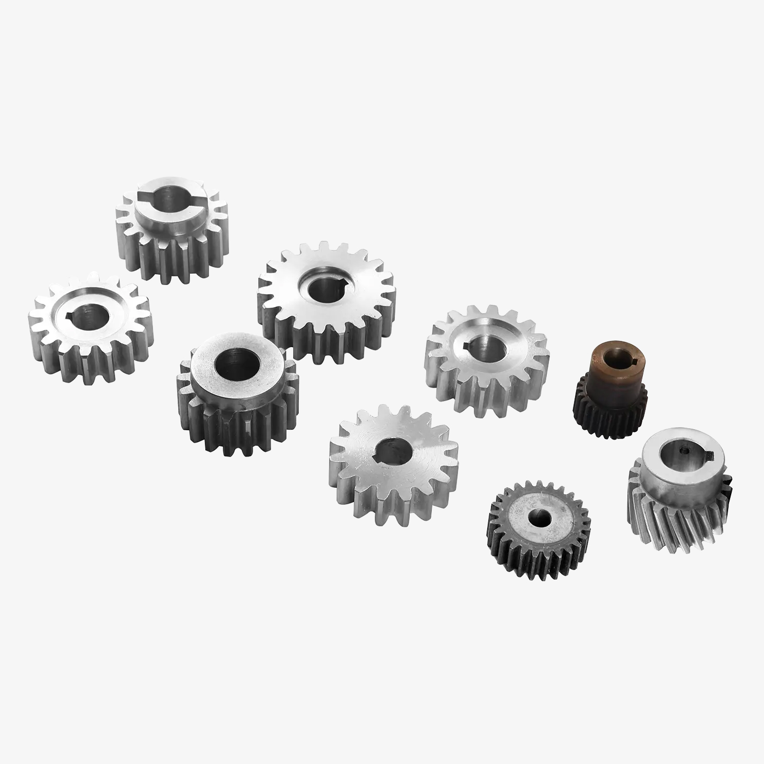
Precision in stepped rack pinion gears primarily depends on the manufacturing processes and quality control measures. The teeth must be cut with exact dimensional accuracy to maintain consistent spacing and profile along the rack and pinion surfaces. Any deviation in tooth geometry or step transitions can cause vibration, uneven wear, or operational noise.
Advanced machining methods such as CNC milling or gear hobbing are commonly employed to produce stepped racks with tight tolerances. Additionally, heat treatment processes like carburizing or nitriding are applied to enhance surface hardness and dimensional stability, both of which contribute to maintaining precision under load.
The stepped design necessitates careful alignment between the pinion and each rack segment. This demands precise mounting and inspection during installation to avoid misalignment, which would degrade performance.
In practical applications, such as industrial automation or machine tools, the precision level of stepped rack pinion gears directly influences operational accuracy and reliability. Therefore, manufacturers often specify precision classes that comply with international standards like ISO or AGMA, providing users with confidence in their gear's performance.
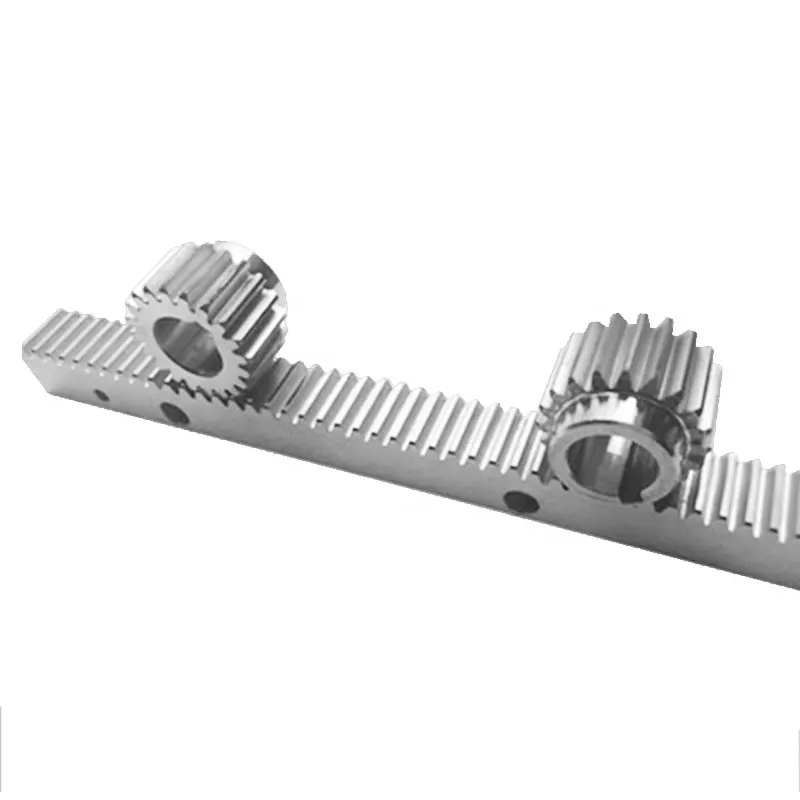
The gear teeth of a straight teeth rack pinion gear system are fundamental to its ability to convert rotational motion into linear motion efficiently and reliably. These teeth are cut perpendicular to the gear's axis, providing straightforward engagement with the mating pinion.
Straight teeth gears are generally simpler in design compared to helical or bevel gears, which contributes to easier manufacturing and lower costs. However, they also come with specific mechanical characteristics. The meshing of straight teeth occurs instantaneously across the entire tooth width, which can generate more noise and vibration during operation compared to angled or helical teeth.
The geometry of the teeth—including pitch, depth, pressure angle, and module—must be carefully designed and manufactured. These parameters determine load capacity, backlash, wear rate, and the smoothness of gear engagement. A uniform tooth profile ensures consistent force transmission and minimizes the risk of premature gear failure.
Material choice affects the durability of the gear teeth. Steel alloys, often hardened, are common due to their high strength and wear resistance. In some applications, plastic or composite materials may be used for quieter operation and reduced weight but typically at lower load capacities.
Maintenance of straight teeth rack pinion gears includes regular lubrication to reduce friction and wear. Despite the potential for increased noise, their simplicity and effectiveness make straight teeth rack pinion gears widely used in various industrial and mechanical systems.
Sliding gate hardware refers to the collection of mechanical components that enable a gate to move smoothly and securely along a defined path. These components are essential for both manual and automated sliding gate systems and contribute to operational stability, safety, and longevity.
Key sliding gate hardware includes rollers or wheels, which bear the gate's weight and allow it to roll along a track. These wheels are often made from durable materials such as nylon, steel, or cast iron and may be fitted with bearings to reduce friction and ensure smooth movement.
The track or rail provides the pathway for the wheels and can be made of galvanized steel, stainless steel, or aluminum. The track profile varies depending on the wheel type—common profiles include V-shaped, flat, or U-shaped.
Guides or guide rails stabilize the gate laterally, preventing it from swaying or coming off the track, especially important in windy conditions or with heavier gates.
Stops or bumpers are installed at the ends of the track to prevent the gate from sliding beyond its limits, protecting both the gate and surrounding structures.
The Multiple Specifications Rack Pinion Gear is a versatile mechanical...
See Details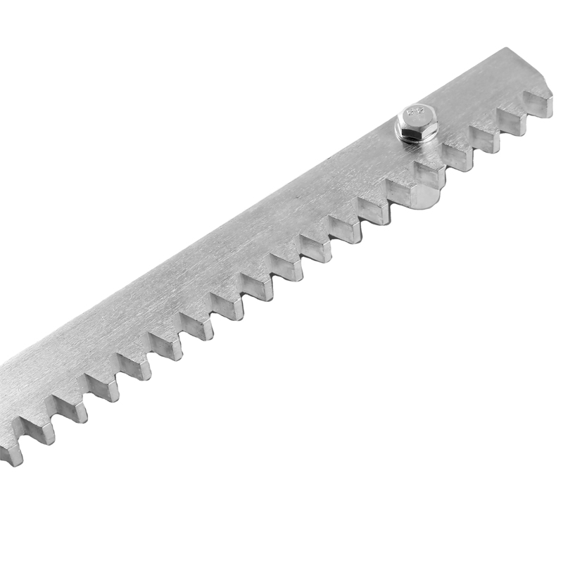
The Mounting Holes Sliding Door Steel Gear Rack is a critical componen...
See Details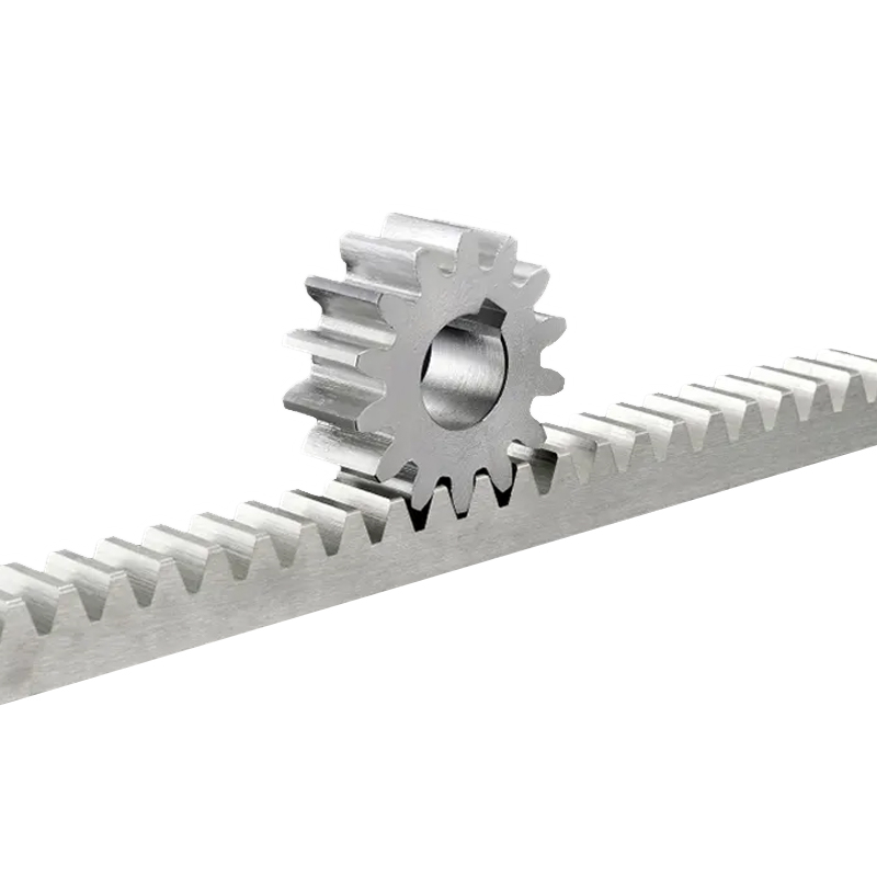
The stainless steel sliding door steel gear rack is an essential compo...
See Details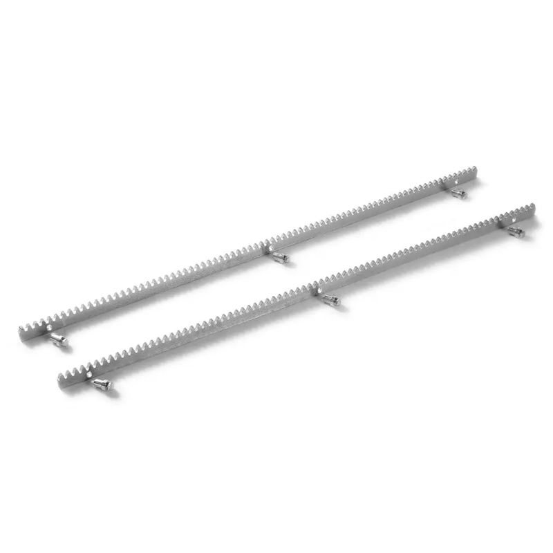
The Durable High-Quality Sliding Door Steel Gear Rack is a versatile a...
See Details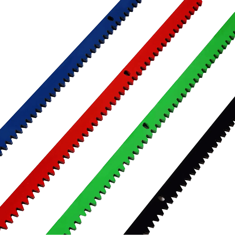
The Color Customization Sliding Door Steel Gear Rack is a highly funct...
See Details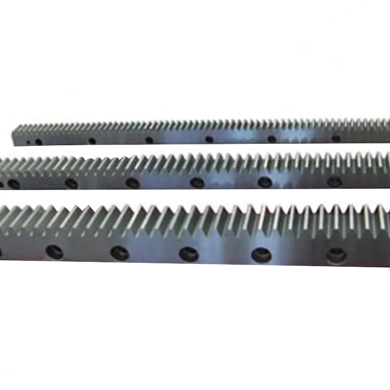
The Spiral Cone Various Specifications Helical Gear Rack is a type of ...
See Details
New Durable Custom Helical Gear Rack is a mechanical transmission ...
See Details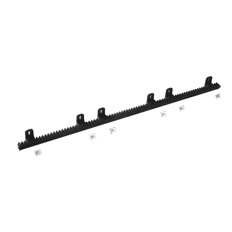
The Black Six Eyes Sliding Door Nylon Gear Rack is a versatile and pra...
See Details