 English
 русский
 Español
No. 200 Gaoxin RD, Shanghua St, Lanxi, Zhejiang, P. R China
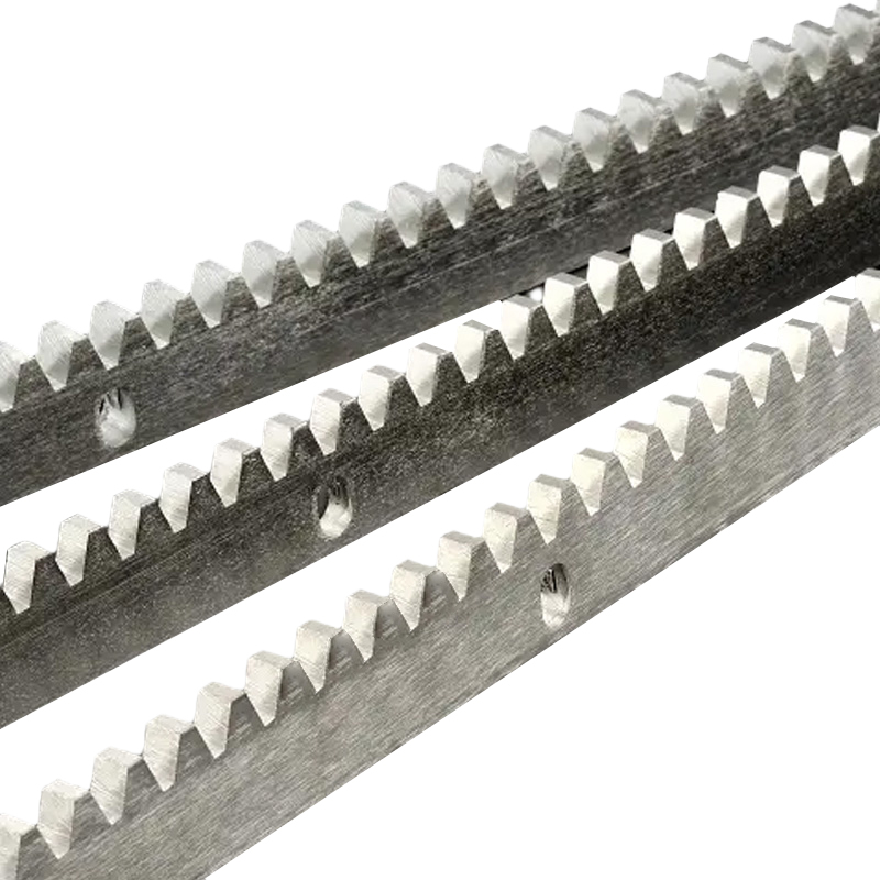
Surface heat treatment rack pinion gear is a mechanical transmission c...
See DetailsHelical Gear systems do not behave in a uniform way across all operating conditions. The difference mainly comes from how the tooth contact develops and how the load is carried during rotation.
At higher speed, the engagement between teeth does not happen all at once. Instead, contact begins gradually along the angled tooth surface and shifts smoothly as rotation continues. This kind of interaction reduces sudden impact between mating surfaces and allows motion to feel more continuous.
At lower speed with higher torque, the situation changes. The contact area tends to stay more concentrated for a longer moment, and the load is carried through fewer active contact zones at any given time. This makes the system more sensitive to alignment and structural stiffness, especially in Helical Gear setups where force direction is not purely radial.
The helix angle plays a direct role in shaping how a Helical Gear behaves during operation. It defines how strongly the tooth line is twisted along the gear body, which affects both motion transfer and force direction.
When the angle becomes larger, the engagement between teeth overlaps more across the gear face, which helps the rotation feel more continuous. At the same time, this geometry introduces a stronger force component along the shaft direction, meaning the supporting structure must take this into account. When the angle is smaller, the axial influence is reduced, but the contact transition becomes less gradual.
| Helix angle condition | Motion character | Axial force behavior | Structural demand |
|---|---|---|---|
| Lower inclination | More direct contact | Lower axial effect | Simpler support requirement |
| Higher inclination | More overlapping contact | Higher axial effect | Stronger axial support needed |
In Helical Gear design, the choice of helix angle is usually a balance between smooth motion behavior and how much axial load the system can reasonably handle.
A key feature of Helical Gear operation is that tooth contact does not switch abruptly from one pair to another. Instead, engagement moves progressively along the tooth surface, allowing more than one contact zone to share the load during rotation.
This gradual transfer of force helps reduce sudden changes in motion behavior. Over longer running cycles, this leads to a more even distribution of mechanical stress across the tooth surface. The system does not rely on a single instant of contact, which helps maintain a more controlled motion pattern under varying load conditions.
Because of this continuous engagement, the overall behavior tends to remain more stable when the system operates for extended periods, especially in applications where rotational consistency is important.
Helical Gear structures are often used in systems where motion quality is a key consideration. The angled tooth design supports smoother engagement, which helps reduce abrupt changes during rotation and contributes to a more controlled mechanical response.
In practical use, these gears are commonly found in transmission layouts where power is transferred through multiple stages, as well as in conveyor-driven systems where motion needs to remain steady under changing load conditions. They are also used in rotating equipment where vibration levels need to be kept within a controlled range to protect surrounding components.
The selection of Helical Gear in these environments is usually connected to how the system behaves dynamically rather than only how much torque it can transmit.
In a Helical Gear, the tooth line is not parallel to the shaft. Because of this angled shape, the contact force during meshing does not act in a single direction. Part of it drives rotation, while another part naturally appears along the shaft axis.
This axial force is not an added effect from outside. It comes directly from how the tooth surfaces slide into contact. As the gear turns, the contact point moves along the helix, which creates a pushing tendency along the axis. The size of this force depends on how steep the tooth angle is and how much load is applied.
For mechanical layout, this means the shaft is not only carrying rotational load. It also needs to hold position against axial movement. Bearings and housing alignment become part of the overall load path in Helical Gear systems.
When a Helical Gear runs at lower speed but carries higher torque, the way forces appear on the tooth surface changes. The contact area does not shift quickly. Instead, it stays in a more fixed zone for a longer time.
This makes the load feel more concentrated on specific areas of the tooth surface. Small alignment changes can have a stronger effect on how the load is shared. At the same time, the axial force that exists in all helical structures becomes more noticeable because the system is under sustained pressure rather than short engagement cycles.
In this kind of working condition, the stability of shafts, supports, and bearings becomes more critical for keeping motion steady.
How contact pattern shifts across different speed ranges in operation
| Operating condition | Contact movement | Load distribution | Surface behavior |
|---|---|---|---|
| Higher speed | More gradual shifting along tooth face | More spread across surface | Smoother interaction pattern |
| Lower speed | More fixed contact zone | More concentrated load | Higher local pressure |
A Helical Gear system depends on both geometry and operating support conditions. The angled tooth structure creates sliding contact, so lubrication plays an important role in keeping the surfaces stable during motion.
Design choices such as tooth width, angle selection, and material pairing influence how the load is shared. At the same time, lubrication helps maintain a thin protective layer between surfaces, especially when the system moves between different speed conditions.
Some practical points include keeping alignment stable, ensuring lubrication reaches the full contact area, and selecting a tooth angle that matches the expected load direction. These factors help the system stay consistent during operation.
In many transmission setups, these design choices are part of the overall engineering work carried out around Helical Gear applications, including configurations associated with Zhejiang Luxin Door Operation Equipment Co., Ltd.
Surface heat treatment rack pinion gear is a mechanical transmission c...
See Details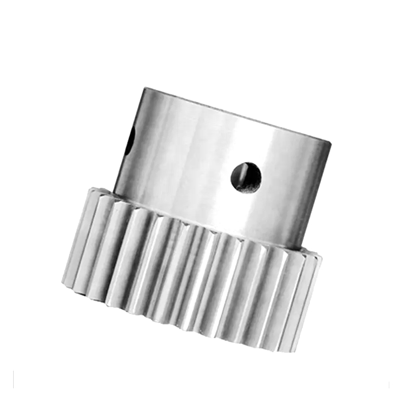
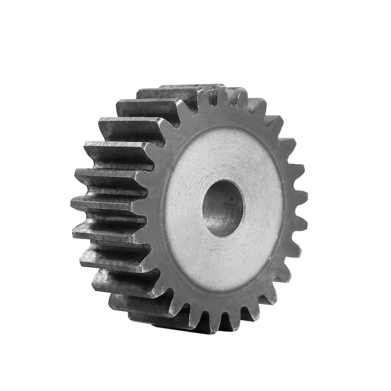
The Stainless Steel Stepped Rack Pinion Gear is a highly versatile and...
See Details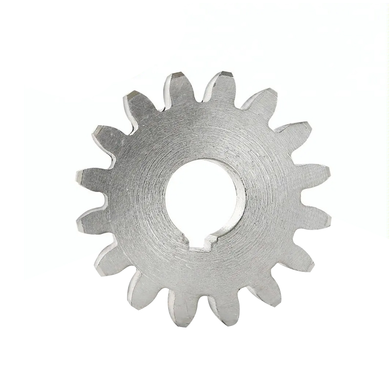
The Smooth Surface High Precision Rack Pinion Gear is a high-performan...
See Details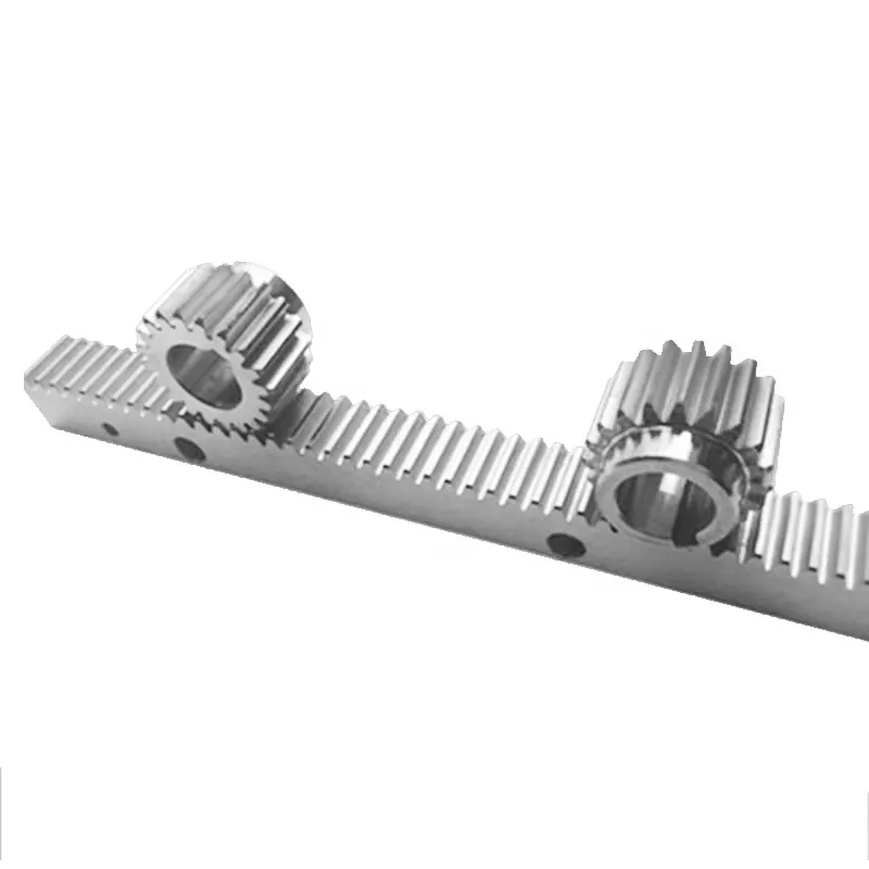
The Multiple Specifications Rack Pinion Gear is a versatile mechanical...
See Details
The High Precision Gear Shaft Rack Pinion Gear is a vital component in...
See Details
The Color Customization Sliding Door Steel Gear Rack is a highly funct...
See Details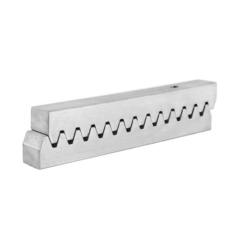
The Square Evenly Distributed Straight Gear Rack is a precision mechan...
See Details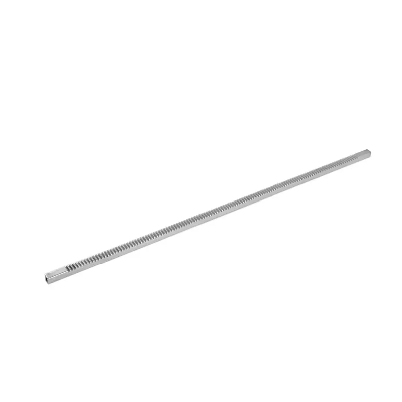
Industrial Wear-Resistant Straight Gear Rack is a linear transmission ...
See Details