 English
 русский
 Español
No. 200 Gaoxin RD, Shanghua St, Lanxi, Zhejiang, P. R China
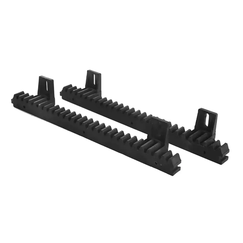
Surface heat treatment rack pinion gear is a mechanical transmission c...
See DetailsA rack and pinion system that passes initial installation looks complete — but the moment of truth comes when it operates under load. Noise that was not there during setup, a gate that stutters at certain points in its travel, or a motor drawing more current than expected are all familiar symptoms to anyone who has worked through a post-installation problem. These are rarely caused by defective components. They trace back to alignment errors that were present from the start and compound with every operating cycle. Whether the installation involves a Nylon Rack for Sliding Gate applications or a steel gear rack in a heavier industrial system, the alignment checks that happen after installation determine how long the system performs reliably.
A gear rack and pinion assembly works by maintaining continuous meshing contact between the rack teeth and the pinion gear. When that contact is consistent across the full travel length, the system delivers smooth linear motion with predictable force transmission. When alignment is off — even by a small margin — the contact pattern changes at different points along the rack, introducing variation in load, friction, and tooth wear that the system was not designed to handle.
The consequences of uncorrected misalignment compound over time:
A Precision Gear Rack cannot compensate for poor alignment — its dimensional accuracy is a prerequisite for good meshing, not a substitute for correct installation and adjustment.
Before any electrical commissioning, a methodical physical inspection covers the conditions that alignment tools will later quantify. These checks take minutes and identify obvious errors before they become powered problems.
Check the rack mounting surface:
Check the pinion gear position:
Check the rack joint connections:
Engagement depth — how far the pinion tooth penetrates into the rack tooth space — affects both load capacity and noise. Insufficient engagement means the teeth carry load on their tips, which concentrates stress and produces rapid wear at the tooth crest. Excessive engagement forces the teeth into the root of the opposing tooth space, which creates interference and can lock the system under load.
The correct engagement depth puts the pitch line of the pinion at the pitch line of the rack — a theoretical plane that represents the rolling contact point where the tooth surfaces are tangent. For practical installation, the manufacturer's specified center distance between pinion shaft and rack mounting surface provides the target engagement depth.
To check and adjust:
A rack installation that is straight at its ends may have intermediate deflections or bow that are invisible until the pinion reaches that section. Straightness errors create local misalignment zones where engagement quality degrades without the installation appearing obviously wrong.
Checking full-length rack straightness:
Backlash is the clearance between the meshing teeth — the small amount of play that exists in a properly assembled gear system to prevent jamming under thermal expansion and manufacturing tolerance accumulation. Too little backlash causes the teeth to bind; too much backlash allows position error to accumulate and produces noise on direction reversal.
For sliding door gear rack and sliding gate systems, backlash has direct implications for gate positioning accuracy and noise during operation:
A gate or sliding door that is heavier at one end than the other, or that has wheels in different states of wear or adjustment, creates uneven load distribution along the rack length. The sections of rack under the heavier load carry more tooth stress and will wear faster than sections under lighter load.
After alignment, checking load distribution involves:
The alignment procedure is fundamentally the same for nylon and steel racks, but the properties of each material create different sensitivities during the alignment process and different tolerances for alignment error during operation.
| Factor | Nylon Rack for Sliding Gate | Stainless Steel Gear Rack |
|---|---|---|
| Noise sensitivity to misalignment | Lower — nylon absorbs minor irregularities | Higher — metal-on-metal contact amplifies errors |
| Engagement depth tolerance | Slightly more forgiving due to material compliance | Tighter — steel has no compliance to absorb errors |
| Backlash requirements | Can tolerate slightly wider backlash | Requires tighter backlash for precision applications |
| Thermal expansion | Greater expansion coefficient — check in temperature extremes | Lower expansion — more stable across temperature range |
| Wear pattern under misalignment | Gradual surface wear, visible as whitening or roughening | Progressive chipping and surface hardening |
| Lubrication requirement | Typically self-lubricating or reduced lubrication | Requires appropriate lubrication for metal contact |
| Alignment verification frequency | Less frequent in stable conditions | More frequent in high-cycle or load-variable applications |
A Nylon Rack and Pinion system will often continue to operate through alignment errors that would produce audible problems immediately in a steel system — but that resilience should not be read as indicating that alignment does not matter. Surface wear in nylon accumulates silently and becomes visible only when the tooth profile has already degraded meaningfully.
A steel rack and pinion system shows alignment problems faster, but that immediate feedback allows correction before significant damage occurs, provided the installation team knows to check for it.
Several symptoms appear regularly in rack and pinion systems where alignment was not adequately verified after installation. Each symptom points to a specific type of alignment error:
Intermittent clicking or tapping during travel: Indicates a pitch error at a rack joint, a loose fastener creating a compliance point, or debris caught between the teeth. Check all joints and fastener torque before investigating other causes.
Constant grinding or scraping noise: Indicates engagement that is too deep, or contact between pinion or mounting hardware and the rack body outside the tooth profile. Check center distance and verify that no part of the mounting hardware interferes with rack geometry.
Gate or door stalling at specific locations: Points to a localized alignment error — a rack section that bows, a joint that creates a step, or a wheel on the gate that runs high at a specific point. Identify the travel position of stalling and examine the rack section at that position.
Motor overload signals: Consistent motor overload in a system that previously operated within normal parameters indicates increasing mechanical resistance — typically caused by wear debris accumulation, fastener loosening, or progressive misalignment as mounting surfaces settle.
Uneven tooth wear: Inspectable by comparing tooth profiles at different points along the rack. Sections with heavier wear indicate either higher local load or misalignment that concentrates contact stress at those positions.
Vibration transferring into the gate structure: Vibration that is felt in the gate frame or door panel rather than isolated to the drive system indicates irregular meshing — the gate or door is acting as a resonator for drive train irregularities that well-aligned meshing would not produce.
Where a Precision Gear Rack is installed in an application that requires tight positioning accuracy — automated industrial gates, controlled access systems, or high-cycle commercial doors — the adjustment process goes beyond basic alignment and addresses the accumulated tolerance chain across the full system.
A structured fine adjustment sequence:
Post-installation alignment verification is not a one-time task. A system that is correctly aligned at commissioning will drift as fasteners settle, mounting surfaces bed in, and operating loads create minor but cumulative shifts in the installation.
A practical maintenance schedule for sliding door gear rack and gate systems:
What is the correct alignment for a rack and pinion system? The goal is consistent engagement depth along the full rack length, with the pitch lines of rack and pinion coinciding and backlash within the manufacturer's specified range. Straightness of the rack mounting surface should be within the specified tolerance for the rack module and application.
How do you test gear engagement without specialist tools? Marking compound applied to several teeth, then running the pinion through the marked section, reveals the contact pattern directly. Correct engagement shows a contact mark centered on the tooth face. Tip contact or root contact indicates center distance error that needs correction.
What is the difference between Nylon Rack for Sliding Gate and steel rack for the same application? Nylon racks are quieter and more tolerant of minor alignment imperfections, which makes them practical in residential and light commercial applications where noise and minor operational imperfection are concerns. Steel racks carry higher loads and tolerate higher cycle counts without surface degradation, which makes them appropriate for heavy-duty or high-cycle gate systems. Alignment matters for both — the consequences of misalignment differ in how quickly they become visible.
How often should alignment be checked in a rack and pinion system? For light-duty residential sliding gate systems: after initial settling and then annually or after any impact event. For commercial and industrial systems: after initial settling, seasonally, and after any significant mechanical event. High-cycle industrial systems may justify more frequent inspection based on operating load and cycle count.
Can different types of rack and pinion be aligned using the same process? The fundamental alignment checks — engagement depth, straightness, backlash, load distribution — apply across different types of rack and pinion configurations. What varies is the tooling used, the tolerance specifications, and the sensitivity of each type to specific alignment errors. A helical gear rack requires attention to the helix angle in addition to the basic checks; a precision rack requires tighter tolerance verification than a standard module rack.
Correct alignment after installing a rack and pinion system is the work that converts a mechanically complete installation into one that will perform reliably across its intended service life. The checks described here — engagement depth, straightness, backlash, load distribution, and the material-specific considerations for nylon and steel racks — each address a specific failure mode that will eventually surface if the check is skipped. For installation teams, fabricators, and sourcing teams evaluating gear rack solutions for sliding gate, sliding door, or industrial automation applications, the alignment process is inseparable from the quality of the hardware being installed. Zhejiang Luxin Door Operation Equipment Co., Ltd. manufactures Nylon Rack and Pinion systems, steel gear racks, and related drive components for sliding gate and door applications, with product range covering residential, commercial, and industrial installation requirements. For technical questions about rack specifications, alignment requirements, or sourcing discussions for specific applications, reaching out to their team provides access to both product expertise and application support.
Surface heat treatment rack pinion gear is a mechanical transmission c...
See Details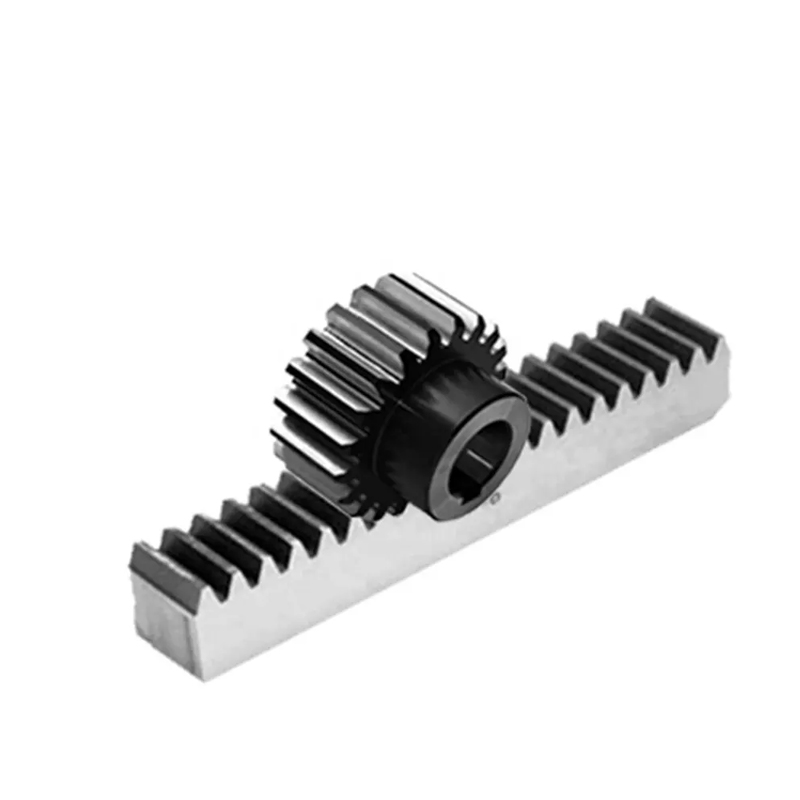
The Rack Pinion Gear for automatic door openers is a crucial component...
See Details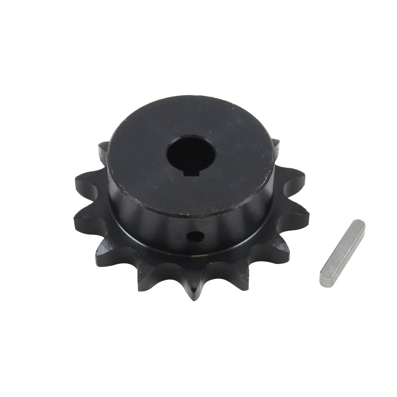
The Roller Transmission Double Plus Rack Pinion Gear is a highly effic...
See Details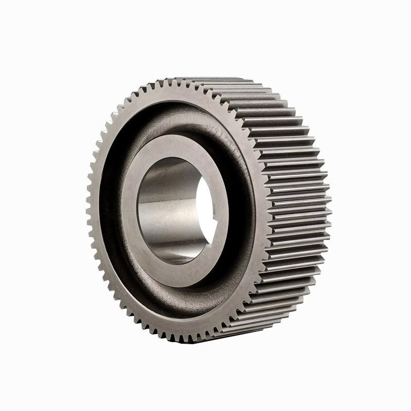
The High Precision Gear Shaft Rack Pinion Gear is a vital component in...
See Details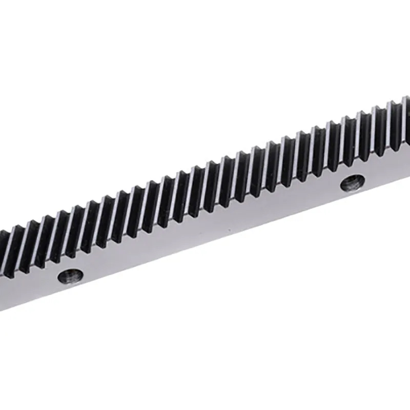
Precision and stainless steel gear racks convert rotational motion int...
See Details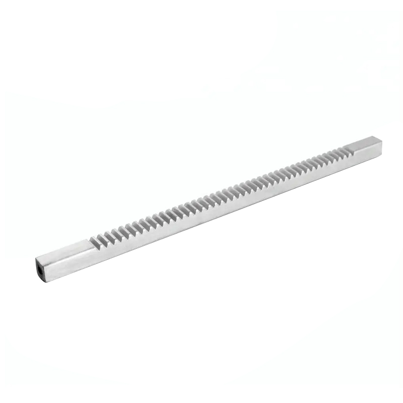
A sliding door gear rack and steel rack and pinion system plays an imp...
See Details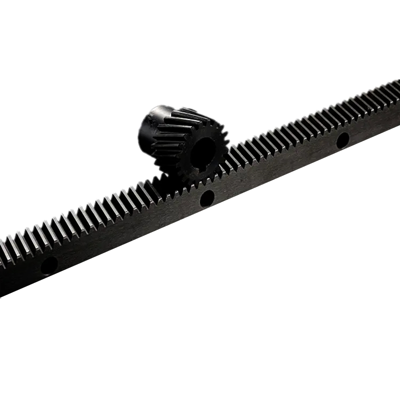
Linear precision guides helical gear rack is a transmission component ...
See Details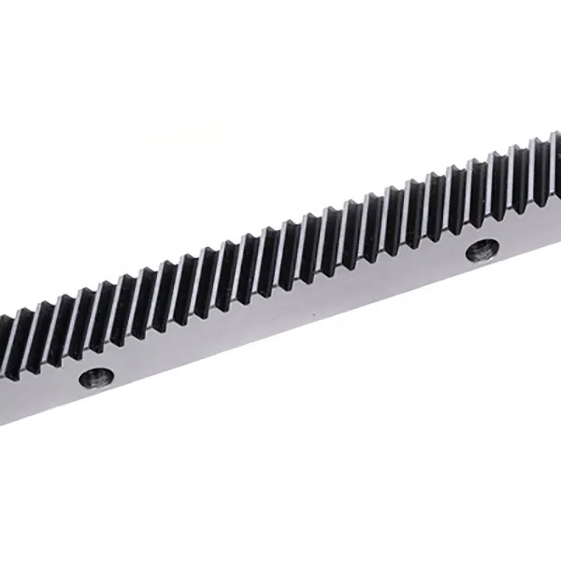
Industrial engraving transmission straight gear rack is a precision li...
See Details