
 English
 русский
 Español
No. 200 Gaoxin RD, Shanghua St, Lanxi, Zhejiang, P. R China
Surface heat treatment rack pinion gear is a mechanical transmission c...
See DetailsRack and pinion setups are common across industrial automation—CNC machines, robots, material handling, packaging lines, positioning platforms. They do one basic job: convert rotary motion into linear movement. Simple structure, high load capacity, flexible configuration. That combination makes them a practical choice when you need controlled travel over long distances.
But not every rack and pinion performs the same. Tooth geometry, manufacturing method, material, mounting—all of it affects positioning accuracy, load capacity, speed, and service life. Knowing the different types helps engineers choose a transmission that actually fits the automation task.
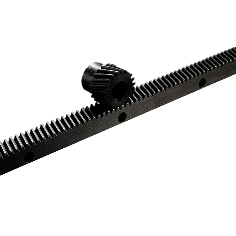
How Rack and Pinion Mechanisms Work in Automation
A rack and pinion system is a straight toothed bar (the rack) meshing with a circular gear (the pinion). Pinion rotates, teeth engage, linear movement happens. Reverse the pinion and the direction flips.
Drive options include electric motors, servo motors, or other rotary sources. In automated equipment, a servo motor with a gearbox and feedback system gives controlled positioning and repeatable motion.
Performance depends on several factors: gear module and tooth geometry, material strength and surface hardness, manufacturing accuracy and backlash, lubrication and environment, rack length, mounting rigidity, alignment. You can't treat these separately—a high-precision gear won't fix poor installation or a flexy structure.
Straight-Tooth Rack and Pinion Systems
Straight-tooth (spur) systems have teeth parallel to the rack's direction of travel. The pinion has matching straight teeth.
This is a common configuration in industrial automation. Straightforward design, relatively simple manufacturing, predictable transmission behavior. Typical applications: automated gates, positioning systems, material handling, general linear actuators, machinery needing moderate accuracy.
Straight-tooth systems mostly generate tangential forces, with little axial thrust from the gear geometry itself. That simplifies bearing and support design. At higher speeds, tooth engagement can produce more vibration and noise—depends on accuracy, loading, lubrication.
Helical Rack and Pinion Systems
Helical systems use angled teeth that engage progressively as the pinion turns. Gradual engagement generally means smoother motion and lower noise than comparable straight-tooth setups.
You'll see helical designs in high-speed CNC equipment, precision positioning platforms, automated production machinery where smooth movement matters. Advantages: more gradual tooth engagement, reduced vibration under suitable conditions, higher potential load capacity for similar gear dimensions, better motion smoothness at speed.
One thing to watch: axial thrust. Angled teeth generate forces along the pinion shaft, so bearings and motor support must handle those loads. Helical systems may also need more careful alignment and lubrication.
Ground and Machined Rack and Pinion Systems
Rack and pinion can also be classified by manufacturing and finishing. That distinction matters when positioning accuracy and transmission consistency are critical.
Machined racks come from cutting processes like hobbing or shaping. They suit many general industrial applications and balance cost against performance.
Ground racks get additional precision grinding to improve tooth profile accuracy, surface finish, dimensional consistency. Common in high-precision CNC machines and positioning systems.
The choice depends on required accuracy, speed, load, budget. Grinding improves transmission performance, but it won't eliminate backlash, installation errors, or structural deformation.
Different Materials Used in Rack and Pinion Manufacturing
Material affects strength, wear resistance, corrosion behavior, maintenance. Industrial racks and pinions are commonly made from different steel grades, stainless steel, or engineering plastics.
| Rack and pinion material | Main characteristics | Typical applications |
|---|---|---|
| Carbon steel | Good strength and cost efficiency | General industrial machinery |
| Alloy steel | Higher strength and heat-treatment options | Heavy-duty automation |
| Stainless steel | Improved corrosion resistance | Food and chemical environments |
| Engineering plastic | Lightweight and quieter operation in suitable loads | Light-duty positioning systems |
| Surface-hardened steel | Improved tooth surface wear resistance | High-cycle transmission systems |
Material selection should account for actual loads, environmental exposure, temperature, lubrication, expected service life. Stainless steel may fit corrosive environments, but grade and surface treatment still need to match the application.
Comparing Common Rack and Pinion Types
| System type | Key advantage | Main consideration | Suitable application |
|---|---|---|---|
| Straight-tooth | Simple design and economical production | Potentially higher noise at speed | General automation |
| Helical | Smooth and quiet engagement | Generates axial thrust | High-speed machinery |
| Machined | Cost-effective manufacturing | Accuracy depends on process quality | Standard positioning |
| Ground | High tooth accuracy and finish | Higher production cost | Precision CNC equipment |
| Plastic | Lightweight and low noise | Limited load and temperature capability | Light-duty automation |
These categories describe design characteristics. A system can combine them—a ground helical rack from hardened alloy steel, for example. Engineers should evaluate tooth geometry, precision grade, and material separately.
Key Factors for Selecting a Rack and Pinion System
Start with the machine's operating requirements. Calculate required linear force, travel distance, speed, acceleration, duty cycle. Those values determine gear module, pinion size, material, motor capacity.
Backlash matters too. Excessive backlash reduces positioning repeatability, especially with frequent direction changes. Preloaded arrangements or backlash-reduction designs can help, though they may increase friction and affect efficiency.
Installation quality is just as important. Rack alignment, mounting surface flatness, pinion engagement depth, lubrication—all influence performance. Long racks may need multiple sections, so joint alignment and thermal expansion become design considerations.
Maintaining Reliable Performance in Automated Machinery
Regular inspection prevents premature wear and unexpected downtime. Monitor tooth wear, unusual noise, vibration, lubrication condition, mounting fasteners, backlash changes.
Lubrication intervals should follow manufacturer recommendations and account for speed, load, environment, contamination. In demanding applications, condition monitoring can catch developing problems before they affect accuracy.
Selecting the correct rack and pinion configuration requires balancing precision, load capacity, operating speed, environmental conditions, and total ownership cost. By understanding the Different Types of Rack and Pinion and their engineering characteristics, manufacturers can build automation systems with more predictable motion, reliable positioning, and longer service life.
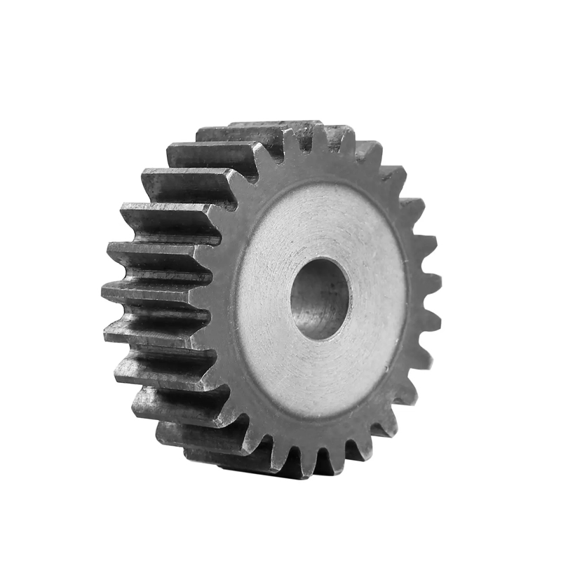
Surface heat treatment rack pinion gear is a mechanical transmission c...
See Details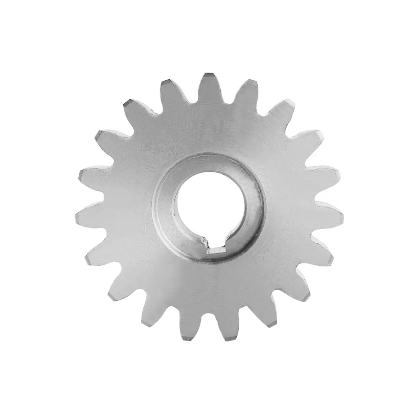
The Stainless Steel Rack Pinion Gear for Sliding Motors is a high-prec...
See Details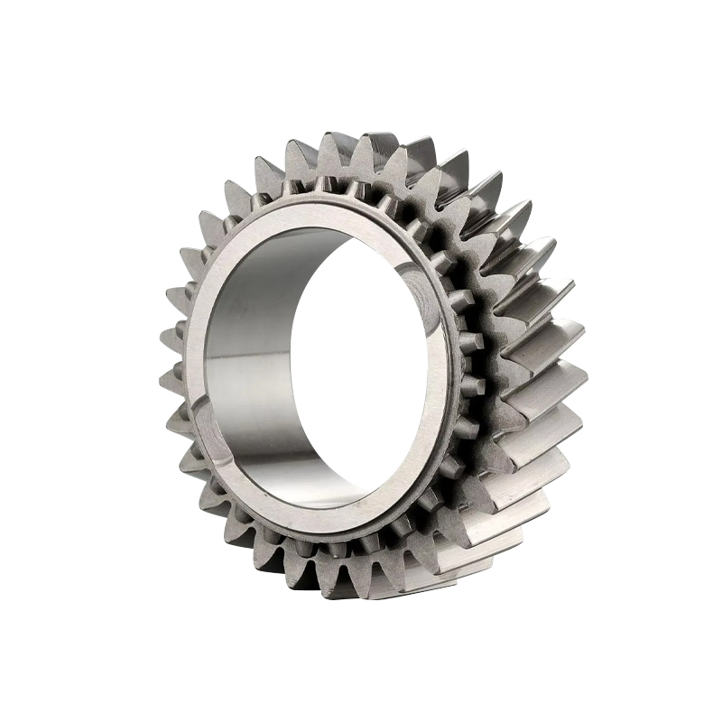
The Gearbox Transmission Rack Pinion Gear system is a critical mechani...
See Details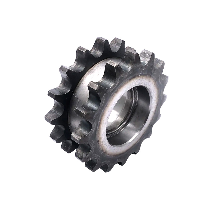
The Double Pitch Sprocket Rack Pinion Gear is a specialized mechanical...
See Details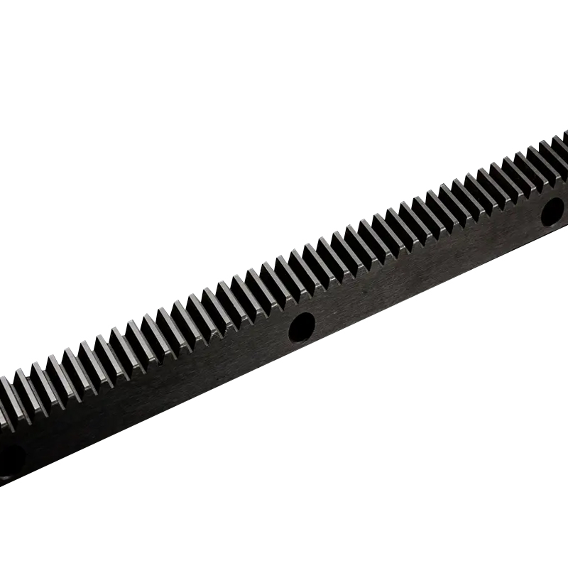
The Precision Durability Sliding Door Steel Gear Rack is a high-perfor...
See Details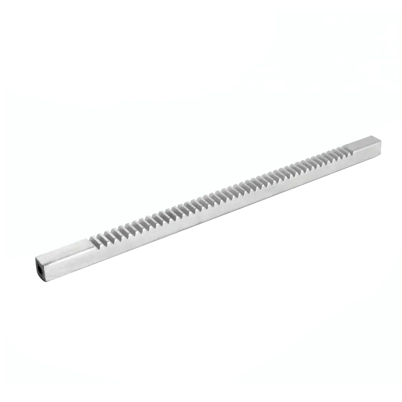
A sliding door gear rack and steel rack and pinion system plays an imp...
See Details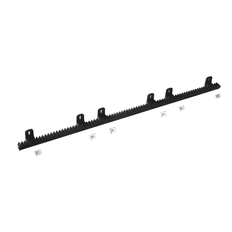
The Black Six Eyes Sliding Door Nylon Gear Rack is a versatile and pra...
See Details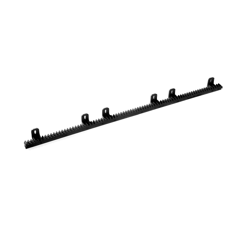
The plastic nylon gear rack for automatic sliding doors is an essentia...
See Details
