
 English
 русский
 Español
No. 200 Gaoxin RD, Shanghua St, Lanxi, Zhejiang, P. R China
Surface heat treatment rack pinion gear is a mechanical transmission c...
See DetailsA gear rack may appear uncomplicated, yet small changes in tooth geometry, mounting position, material, or section length can alter the way it works. A rack made for one sliding gate may not align correctly with another motor, even when both products look similar. A Nylon Gear Rack Factory can adapt selected features around an existing drive system or a new equipment design. Useful customization usually begins with the mating pinion, movement path, mounting surface, operating environment, and production plan.
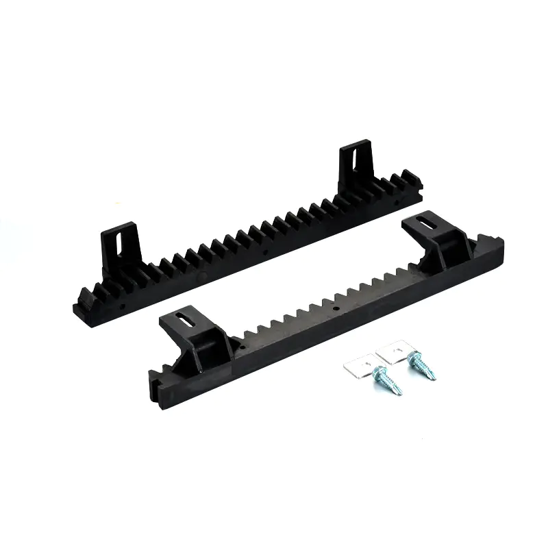
Standard rack sections suit many common installations, but they do not cover every machine frame or gate structure. Buyers may already have fixed mounting holes, limited clearance, a defined pinion, or an enclosure that leaves little room for adjustment.
Changing the surrounding equipment can involve extra drilling, new brackets, or a revised motor position. Adapting the rack may provide a more practical route when the required changes remain suitable for manufacturing.
| Application Detail | Possible Rack Adaptation |
|---|---|
| Existing machine layout | Base shape and mounting position |
| Installed pinion | Tooth profile and direction |
| Available installation space | Rack width, height, and section length |
| Brand appearance | Color and marking |
| Outdoor or indoor service | Material formulation and reinforcement |
| Customer production plan | OEM or ODM arrangement |
Customization should solve a defined fit or operating issue. Adding unusual features without a mechanical reason can make sourcing, installation, and replacement harder.
Dimensions affect how the rack sits on the equipment and where its teeth meet the pinion. A dimensional request should include more than the total length because width, base thickness, tooth height, hole location, and reinforcement position may also affect installation.
A Nylon Gear Rack Factory may work from a customer drawing, equipment sample, pinion sample, or agreed interface specification. Drawings are usually more useful when they show reference surfaces and mounting relationships rather than only the outer shape.
| Dimension Area | Practical Purpose |
|---|---|
| Section length | Follows the required movement path |
| Rack width | Fits the available mounting area |
| Rack height | Positions the teeth relative to the pinion |
| Base thickness | Supports mounting and structural behavior |
| Hole spacing | Coordinates with brackets or frame holes |
| End geometry | Helps adjacent sections meet correctly |
Changing one dimension can affect another part of the assembly. A thicker base may improve mounting support but move the tooth line away from the pinion unless the bracket or motor position is adjusted.
The total rack run needs to cover the equipment’s working travel, including the areas required for starting, stopping, and engagement near each end. Measuring only the clear gate opening can leave the rack too short for the actual drive path.
Long runs are commonly assembled from separate sections. Each joint should continue the tooth pattern without creating a step that causes a click or impact whenever the pinion crosses it.
A wider rack may not fit between a gate panel and nearby hardware. Extra height can also change contact depth or bring the rack too close to a cover, guide bracket, or cable route.
Clearance should be checked with the machine fully assembled. Parts that appear well separated in a drawing may move closer together when the gate flexes, the motor operates, or the outdoor temperature changes.
The tooth profile defines how the rack engages with its pinion. A customized rack must match the mating gear in pitch, pressure geometry, tooth shape, and operating direction.
Straight and helical tooth arrangements are not interchangeable. A Helical Gear Rack Factory also needs information about helix angle and direction because the angled teeth must correspond with the mating pinion.
Customization discussions may cover:
A pinion sample can be useful when records for an older machine are incomplete. Sample matching should still be supported by measurement and an application review rather than visual comparison alone.
Helical teeth run across the rack at an angle. The matching pinion needs the corresponding geometry so the contact develops along the intended path.
Using the wrong helix direction can prevent normal engagement. A similar-looking pinion may also sit on the rack while making contact only near an edge, causing noise and uneven wear once the drive begins moving.
Minor mounting changes may be possible through machining or adjustable tooling. A new tooth form or rack body can require a separate mold, cutting setup, or forming process.
Buyers should identify which dimensions are fixed and which remain open for discussion. This avoids unnecessary tooling work and gives the manufacturer a clearer production target.
A Nylon Gear Rack can be adapted through material formulation, reinforcement, mounting style, color, and rack-body geometry. These choices should reflect the actual load, environment, and pinion arrangement.
Nylon is not one uniform material. Different formulations can behave differently when exposed to moisture, temperature changes, sunlight, repeated loading, or cleaning products.
The factory may discuss nylon grades or modified materials suited to a particular production method and service environment. The final choice can influence stiffness, wear behavior, moisture response, molding behavior, and dimensional stability.
Useful application details include:
A material label by itself does not describe the finished rack. Reinforcement, tooth geometry, wall thickness, manufacturing conditions, and mounting design also affect how the component behaves.
Some nylon racks use a metal insert or supporting core. Reinforcement can help the rack maintain its shape and provide secure attachment points, depending on the product structure.
Customization may involve the reinforcement profile, material, position, or connection with the nylon body. Its placement needs consistent control because an off-center insert can affect straightness or mounting behavior.
Color can help a rack match the equipment housing or distinguish one component version from another. It may also support warehouse sorting where several similar racks are stored together.
| Color Use | Practical Purpose |
|---|---|
| Equipment coordination | Matches the visual design of the machine |
| Version identification | Separates different rack specifications |
| Production sorting | Helps workers recognize component groups |
| Brand presentation | Supports an agreed OEM appearance |
| Maintenance reference | Makes a replacement type easier to identify |
Color should not replace labels, drawings, or part references. Two racks with the same color may still have different teeth, inserts, or mounting holes.
Mounting customization helps the rack fit a gate frame, machine carriage, automation rail, or fabricated bracket. Common requests involve hole positions, slot shapes, mounting lugs, backing profiles, and section joints.
The attachment method also needs to keep the tooth line stable. A convenient hole pattern has little value if the rack bends, lifts, or changes its distance from the pinion during operation.
| Mounting Feature | Possible Application |
|---|---|
| Round holes | Fixed attachment to prepared frame points |
| Slotted holes | Allows controlled positional adjustment |
| Molded mounting lugs | Supports direct fitting to compatible brackets |
| Reinforced mounting areas | Distributes fastening force |
| Custom base profile | Follows a defined machine surface |
| Section-end design | Supports alignment between adjacent pieces |
Mounting changes should be reviewed with the gate or machine material. Thin steel tubing, aluminum profiles, solid frames, and polymer panels do not hold fasteners in the same way.
Customized hole spacing can help a replacement rack use existing frame points. Reusing holes may reduce site work, though their condition and position still need inspection.
Old holes may be enlarged, corroded, or misaligned. Copying a damaged mounting pattern into a new rack can carry an existing installation problem into the replacement.
Slots allow the installer to correct the rack position within a controlled range. They are useful when the pinion height or frame line varies slightly along the travel path.
Adjustment should not permit the rack to creep during direction changes. Suitable washers, fasteners, support surfaces, and tightening procedures are needed to keep the selected position.
Some projects use a standard rack with a customized bracket rather than creating a new rack body. This can reduce changes to the tooth component and make later replacement easier.
The bracket should remain rigid under drive force. A flexible bracket can allow the rack to move away from the pinion when the gate starts, stops, or reverses.
A long gate or machine axis may need several rack sections. The factory can adapt section length and end geometry to suit transport, handling, installation access, and tooth continuity.
Longer sections create fewer joints but can be awkward to pack or hold during installation. Shorter pieces are easier to handle, though each added joint creates another alignment point.
Adjacent sections need to preserve the same tooth spacing. Even a small step can create a repeated knock as the pinion passes the joint.
Installers sometimes use a mating pinion or an approved alignment piece across two sections while fixing them. The method should follow the product instructions, especially with helical teeth.
Nylon responds to moisture and temperature. The amount and direction of movement depend on the material, rack construction, exposure, and fastening arrangement.
A factory may specify joint spacing or mounting practices for the selected product. Sections should not be installed with arbitrary gaps because excessive spacing can also interrupt tooth engagement.
Customized packaging can protect teeth, mounting lugs, and straightness during transport. Dividers, end protection, identification labels, and moisture-conscious storage may be included in an OEM supply plan.
Bent reinforcement or damaged section ends can create installation trouble even when the rack left production within its intended specification. Packages should be stored flat or supported according to the supplier’s instructions.
Matching an existing pinion is possible when enough technical information is available. The factory may request drawings, samples, photographs with reference dimensions, or details from the drive-unit manufacturer.
A physical sample helps with inspection, but its condition matters. A worn pinion may no longer represent the original tooth form accurately.
The review can include:
For an older gate, replacing the rack while retaining a badly worn pinion may produce poor contact. Both components should be inspected before a customized rack is approved.
OEM production usually follows a customer-controlled design or agreed specification. The Nylon Gear Rack Factory manufactures the component with defined dimensions, materials, markings, packaging, and inspection requirements.
OEM options may include:
Branding should be positioned where it does not interfere with teeth, mounting, or alignment. Markings also need to remain readable without weakening a loaded section of the rack body.
ODM work involves more design input from the rack manufacturer. The customer may provide the gate concept, drive arrangement, available space, and operating environment rather than a finished rack drawing.
The factory can then propose a rack structure, mounting pattern, material, reinforcement, or section layout for review. Responsibilities for design approval, testing, documentation, and ownership should be agreed before tooling begins.
A typical ODM process can include:
Prototype testing should use a representative gate or machine. Checking an isolated rack on a bench may not reveal frame movement, section-joint noise, or clearance problems during full travel.
A Nylon Gear Rack Factory can adapt dimensions, tooth geometry, material, reinforcement, color, mounting points, section layout, identification, and packaging. OEM work can follow an established customer design, while ODM work can include development support around an equipment concept.
A Helical Gear Rack Factory can also customize angled tooth arrangements, provided the matching pinion and drive structure are defined. Helix direction, tooth geometry, section continuity, and axial loading remain part of that review.
Useful customization keeps the Nylon Gear Rack compatible with the drive rather than turning it into an unnecessarily complicated component. Clear drawings, representative samples, practical installation checks, and controlled revisions help carry the approved design into regular production.
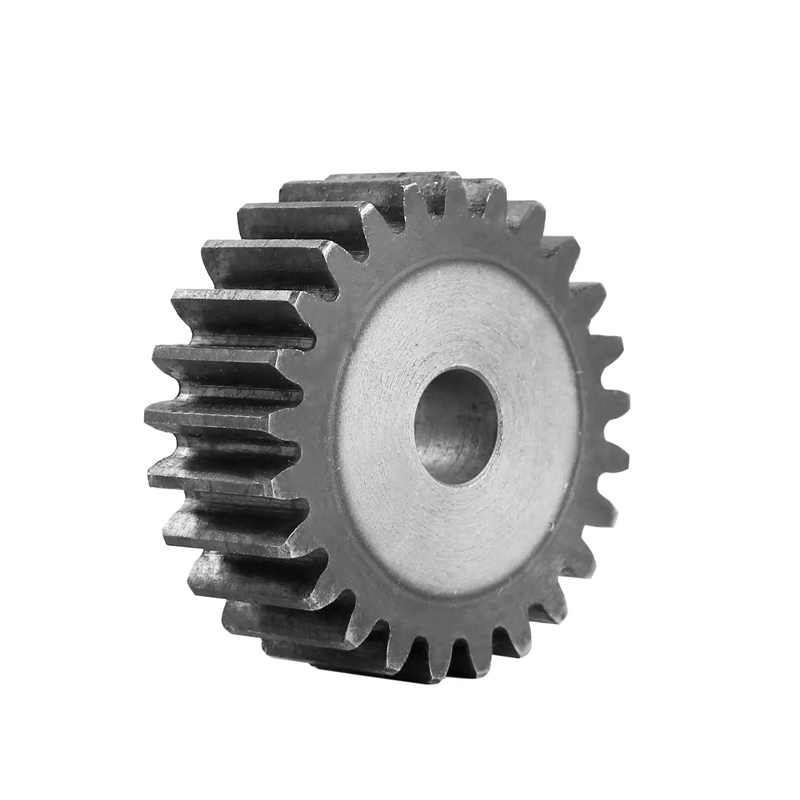
Surface heat treatment rack pinion gear is a mechanical transmission c...
See Details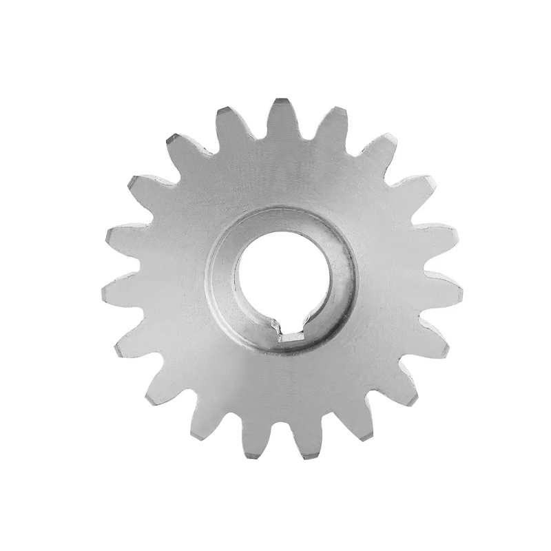
The Stainless Steel Rack Pinion Gear for Sliding Motors is a high-prec...
See Details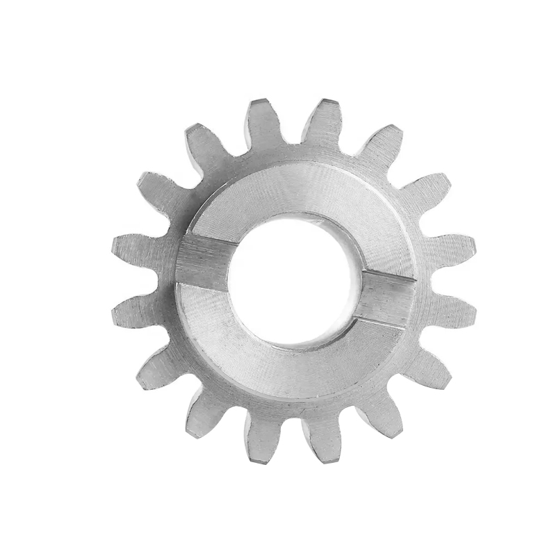
The Sliding Doors Steel Rack Pinion Gear is a critical component in va...
See Details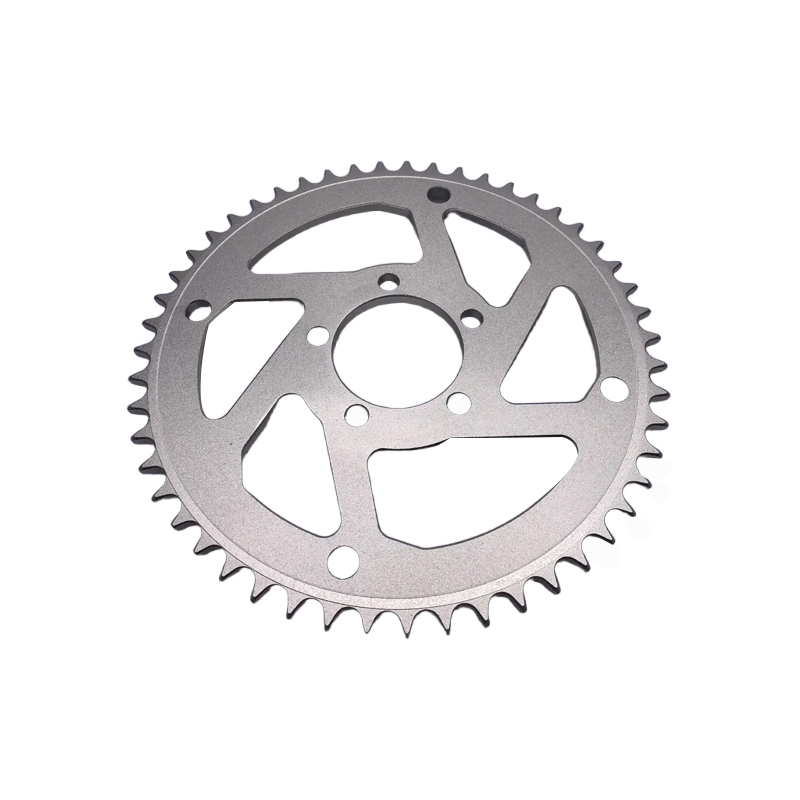
The sprocket drive wheel rack pinion gear is a critical component in v...
See Details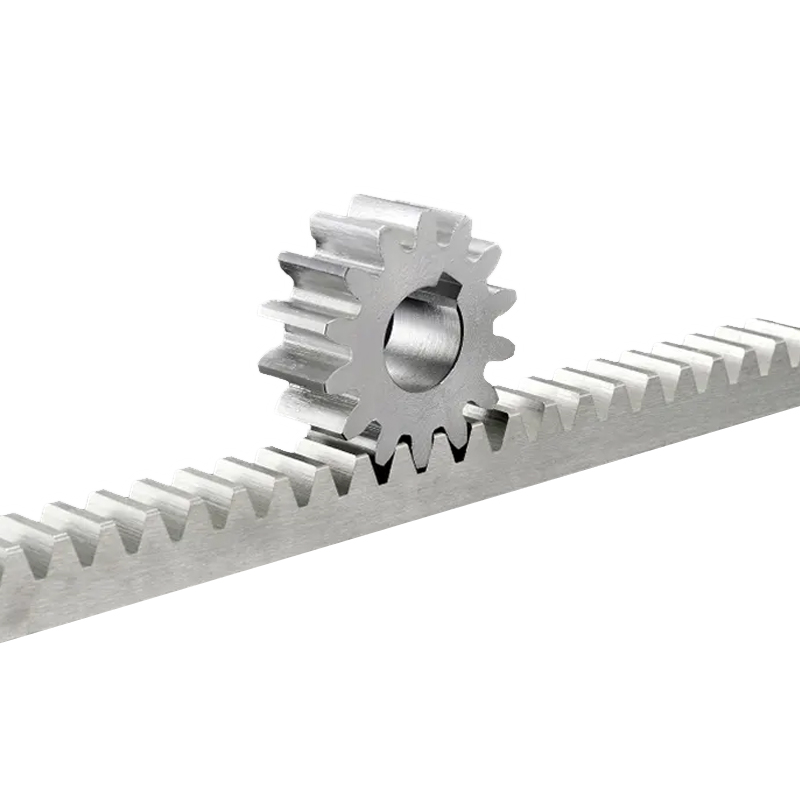
The stainless steel sliding door steel gear rack is an essential compo...
See Details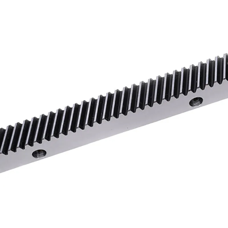
Precision and stainless steel gear racks convert rotational motion int...
See Details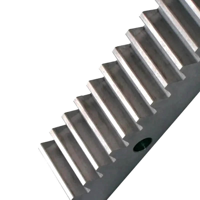
Lifts transmission systems helical gear rack is a key compo...
See Details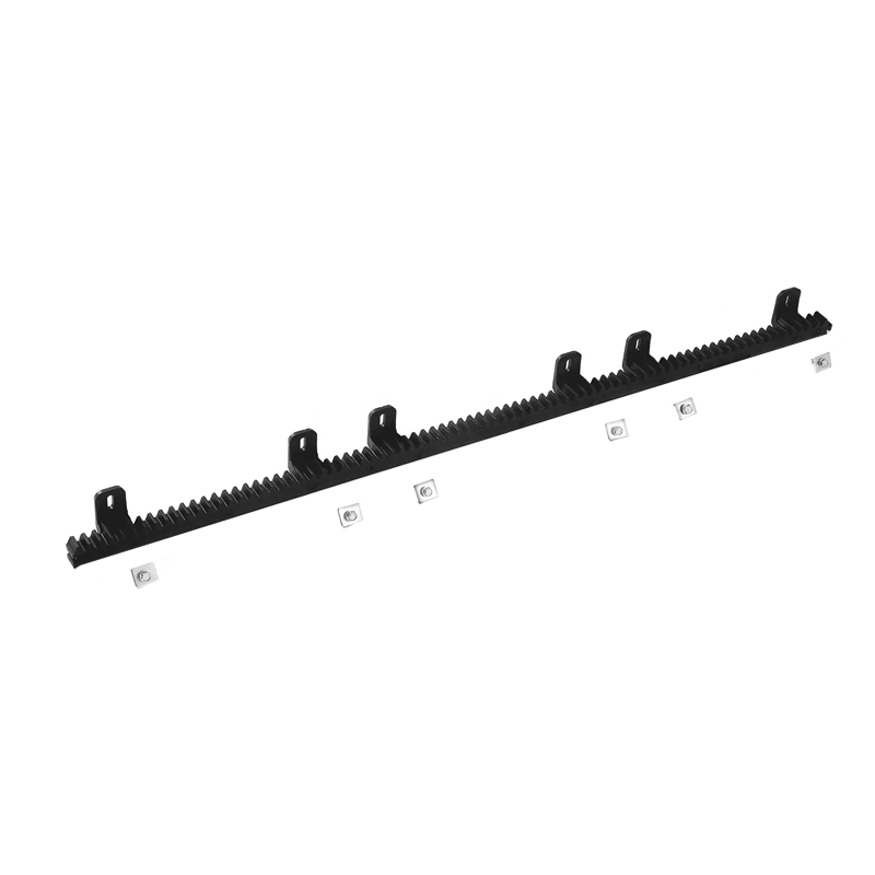
The Black Six Eyes Sliding Door Nylon Gear Rack is a versatile and pra...
See Details
