
 English
 русский
 Español
No. 200 Gaoxin RD, Shanghua St, Lanxi, Zhejiang, P. R China
CNC machine tools sliding doors rack pinion gear is a mechanical trans...
See DetailsHeavy-duty machines need to move large loads without making the whole system complicated. Cranes, gantry systems, CNC equipment, steel-processing machines, industrial doors, and material-handling equipment all have one thing in common: they need controlled movement, often over a fairly long distance.
This is where Gear and Gear Rack systems come into play. A rotating pinion works with a straight rack to turn rotary motion into linear movement. The idea is simple, but getting a rack-and-pinion system to work reliably under heavy loads takes more than choosing two matching gears.
Load, speed, tooth design, material, alignment, lubrication, and the working environment all matter. A system that looks suitable on paper can still have problems if one of these points is overlooked.
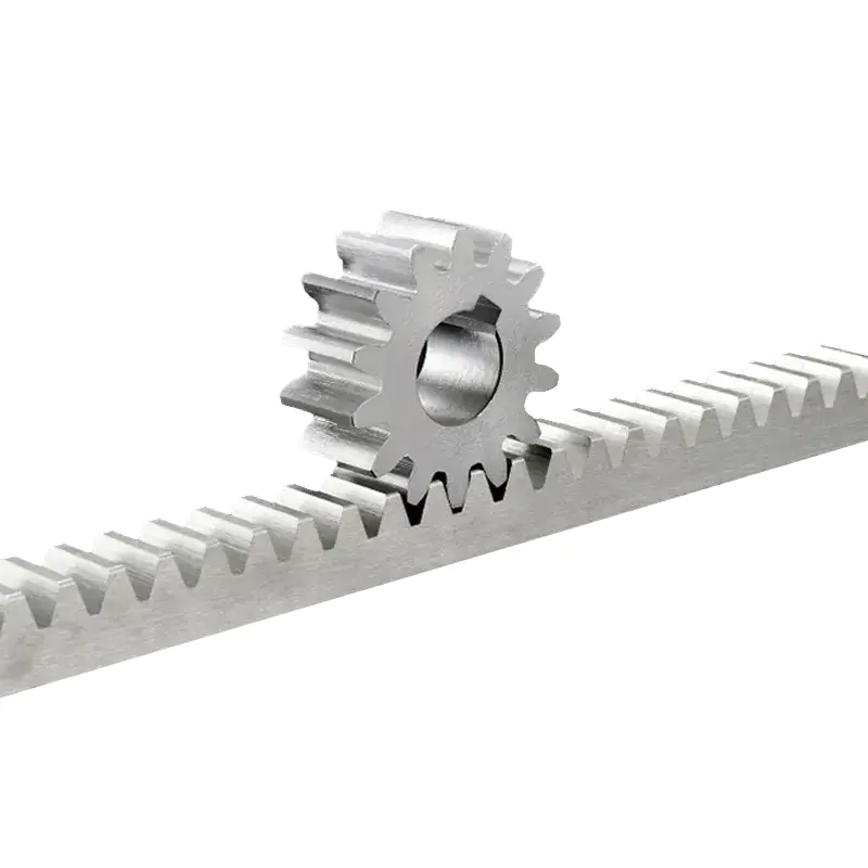
A rack-and-pinion system uses a round gear, usually called the pinion, and a straight toothed rack. When the pinion rotates, its teeth push against the rack and move it in a straight line.
Change the direction of rotation, and the rack moves in the opposite direction. This makes the arrangement useful when a motor or gearbox needs to create controlled linear movement.
The approximate linear travel per pinion revolution can be calculated from:
L = πd
Here, L is the linear travel per revolution and d is the pitch diameter of the pinion.
Of course, real machines are not quite that simple. Tooth geometry, backlash, friction, load, machining accuracy, and efficiency all affect actual movement. Still, the basic relationship is useful when planning the transmission.
One reason rack-and-pinion systems are widely used is their ability to provide linear movement over long distances without making the drive system unnecessarily complicated.
They can be found in:
There are other ways to create linear motion, including ball screws, lead screws, hydraulic cylinders, and electric linear actuators. The right choice depends on the machine.
For long travel, frequent movement, and relatively heavy loads, a rack-and-pinion arrangement can be a practical option.
The actual load should be one of the first things checked. And this means more than the normal weight of the equipment.
A machine carrying 500 kg slowly and steadily does not put the same demands on its rack as a machine moving several tons, stopping suddenly, and starting again dozens of times per hour.
Buyers should consider:
It is easy to look at the physical size of a rack and assume that a larger rack will automatically handle more load. That is not necessarily the case. Tooth size, material, heat treatment, face width, and the way the load is distributed are also important.
The tooth profile controls how the pinion and rack transfer force. Industrial rack-and-pinion systems commonly use involute tooth profiles because they provide predictable engagement when correctly manufactured.
Some of the important parameters include module, pressure angle, tooth height, pitch, face width, and, for helical designs, helix angle.
A larger module generally means larger teeth and greater load-carrying potential. But module alone does not tell the whole story. Two racks with the same module can perform differently if their materials, heat treatments, widths, or operating conditions are different.
The rack and pinion also need to match correctly. Module and pressure angle are particularly important. If these details are wrong, the system may run poorly even if both components appear to be well made.
Straight racks are relatively simple and are used in many standard mechanisms. Their design and installation are usually straightforward.
Helical racks use angled teeth. The teeth engage progressively, which can make the movement smoother and help distribute the load across the tooth contact area. There is a trade-off, though: helical gearing creates axial forces, so the machine structure and bearing arrangement need to account for them.
| Rack Type | Main Characteristic | Typical Use |
|---|---|---|
| Straight rack | Simple tooth arrangement | General industrial mechanisms |
| Helical rack | Gradual tooth engagement | Smoother, higher-load movement |
| Precision rack | Tighter dimensional control | Positioning equipment |
| Heavy-duty rack | Robust construction | High-load machinery |
There is no universal choice here. The machine requirements should decide the rack type.
Material has a direct effect on tooth strength, wear resistance, fatigue performance, and service life.
Carbon steel and alloy steel are common choices for industrial racks. Stainless steel may be considered where corrosion resistance is important, while engineering materials can make sense for lighter or specialized applications.
For demanding equipment, heat treatment is often just as important as the base material. Depending on the design, manufacturers may use hardening, carburizing, nitriding, or induction hardening.
One thing buyers should ask is exactly what “hardened steel” means in the quotation. What material is being used? Which part is hardened? What hardness is required? What treatment process is applied?
Those details are much more useful than a general statement about durability.
Rack length needs to correspond to the machine's required travel. For shorter movement, one rack section may be enough. Long machines often use several rack sections joined together.
This is where installation can become a little tricky.
If several rack sections are connected, their tooth pitch and position have to remain consistent across the joints. The mounting surface also needs to be reasonably straight and flat.
For long-travel systems, buyers should pay attention to:
A small error at one joint may not seem serious at first, but it can cause noise, uneven wear, or positioning problems as the pinion travels along the machine.
Rack and pinion teeth need to engage correctly across the working width. If the components are misaligned, the tooth contact can become concentrated in a small area.
The result may be localized wear, vibration, noise, extra friction, or premature tooth damage.
The machine frame matters too. Even a properly manufactured rack can perform badly if the supporting structure flexes under load.
So installation should not be treated as simply bolting the rack onto the machine and moving on. The rack position, pinion alignment, guide system, and machine frame all work together.
Backlash is the small amount of clearance between mating teeth. Some clearance is necessary because manufacturing tolerances, lubrication, and thermal expansion have to be considered.
Too much backlash, however, can become a problem for machines that need accurate positioning.
CNC machines, automated cutting systems, welding equipment, inspection machines, and other positioning equipment may need tighter backlash control. Heavy material-handling equipment can often accept more clearance.
Depending on the design, adjustable mounting arrangements or special pinion designs can be used to control backlash.
Lubrication is easy to overlook, especially when the rack looks like a fairly simple mechanical part. But the teeth are constantly contacting and transferring force, so friction and wear need to be managed.
Grease is common in many exposed rack systems. Gear oil or automatic lubrication systems may be used in other applications.
For machines running continuously, automatic lubrication can reduce maintenance work. On the other hand, adding too much lubricant is not always helpful. In dusty environments, excessive grease can collect dirt and abrasive particles around the teeth.
The lubrication method should fit the machine, environment, speed, and manufacturer's recommendations.
Machine speed gets plenty of attention, but acceleration and deceleration can be just as important.
A heavy load that moves slowly may still create high tooth forces if the machine starts and stops aggressively. Frequent reversing can add another layer of stress.
| Operating Factor | What It Can Affect |
|---|---|
| Travel speed | Dynamic behavior and wear |
| Acceleration | Tooth loading |
| Deceleration | Transient forces |
| Start-stop frequency | Fatigue and heat |
| Continuous operation | Cumulative wear |
| Load variation | Tooth stress |
For this reason, a machine's actual operating cycle gives the manufacturer more useful information than maximum speed alone.
Industrial equipment rarely operates in a clean laboratory.
Steel mills and foundries may involve heat, dust, and metal particles. Construction equipment can encounter dirt, water, mud, and outdoor exposure. Some chemical-processing environments introduce corrosive substances.
Before selecting the rack, consider:
The material, surface treatment, sealing arrangement, and lubrication method may all need to change depending on these conditions.
Large CNC routers, plasma cutting machines, laser equipment, and other machine tools often need long linear travel. Rack-and-pinion drives can provide the travel needed while maintaining controlled movement.
Here, backlash, positioning accuracy, speed, and rack alignment are usually important.
Gantry systems often move across long rails while carrying substantial equipment or materials. Rack systems provide a practical way to transfer motor rotation into long-distance movement.
Alignment becomes especially important when the machine uses multiple drive points or motors.
Large industrial doors and gates can also use rack-and-pinion mechanisms. The motor rotates the pinion, which moves the rack and therefore the door.
In these applications, load, repeated operation, environmental exposure, and safety controls all need to be considered.
Some construction and specialized machines need controlled mechanical movement under heavy loads. Rack-and-pinion systems can be used where a direct mechanical transmission is suitable.
Because these machines may experience shock and changing loads, mechanical strength and regular inspection are important.
Before placing an order, buyers should provide as much operating information as possible.
| Item | Information to Confirm |
|---|---|
| Travel | Required movement distance |
| Load | Normal and peak load |
| Speed | Required travel speed |
| Acceleration | Start and stop conditions |
| Duty cycle | Operating frequency |
| Geometry | Module and pressure angle |
| Material | Rack and pinion material |
| Heat treatment | Hardness and treatment process |
| Accuracy | Backlash and positioning requirements |
| Environment | Dust, water, heat, chemicals |
| Mounting | Installation method and dimensions |
| Customization | Special sizes or mounting features |
For custom projects, machine drawings or layout files can save a lot of back-and-forth communication. The manufacturer can then check rack length, mounting holes, pinion dimensions, tooth geometry, and other details before production.
Tooth accuracy is not just a number on an inspection report. It affects how the rack and pinion actually contact each other.
Depending on the application, manufacturers may inspect tooth profile, pitch, dimensions, hardness, runout, surface condition, and material properties.
Precision applications may also require inspection reports or dimensional records.
For larger orders, consistency between production batches is worth discussing as well. A rack that matches the drawing but differs noticeably from previous batches can still create problems when it is installed into an existing machine.
Standard racks and pinions work for many machines, but OEM equipment often has its own requirements.
Customization may involve rack length, module, tooth profile, face width, mounting holes, material, heat treatment, surface treatment, or special pinion dimensions.
The important point is that customization should be based on the machine's actual requirements. A manufacturer needs enough information to check whether the requested dimensions, load, accuracy, and production quantity make sense together.
For new designs, sample testing before mass production can also uncover installation or operating issues early.
Before choosing a Gear and Gear Rack system, check these points:
| Factor | What to Check |
|---|---|
| Load | Normal and peak forces |
| Speed | Required travel speed |
| Duty cycle | Operating frequency |
| Geometry | Module and pressure angle |
| Material | Load and environmental requirements |
| Heat treatment | Tooth hardness |
| Accuracy | Backlash and positioning |
| Alignment | Rack and pinion position |
| Lubrication | Maintenance method |
| Customization | Special dimensions or treatment |
A short checklist like this can prevent a surprisingly expensive mistake later.
A rack should not really be selected as an isolated component. It is part of a larger transmission system.
The motor, gearbox, pinion, rack, bearings, guide rails, mounting structure, and control system all affect how the machine behaves. Load and acceleration affect the rack, but frame stiffness and guide alignment can also change the forces reaching the teeth.
For a custom industrial project, it helps to involve the rack manufacturer early. Provide the expected load, travel distance, speed, operating cycle, machine drawings, and environmental conditions.
When those details are considered together, a Gear and Gear Rack system can provide a straightforward way to turn motor rotation into controlled linear movement. The basic mechanism is simple. Making it work reliably on a heavy machine is where the engineering details really matter.
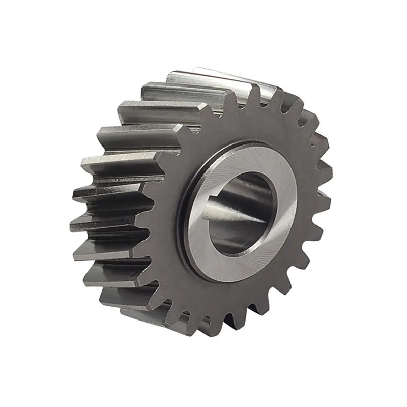
CNC machine tools sliding doors rack pinion gear is a mechanical trans...
See Details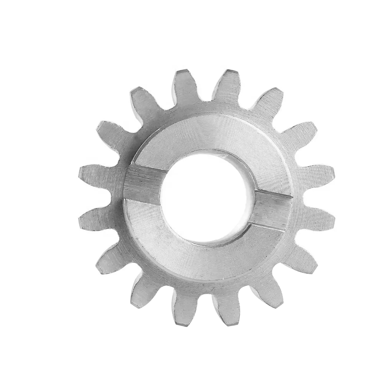
The Sliding Doors Steel Rack Pinion Gear is a critical component in va...
See Details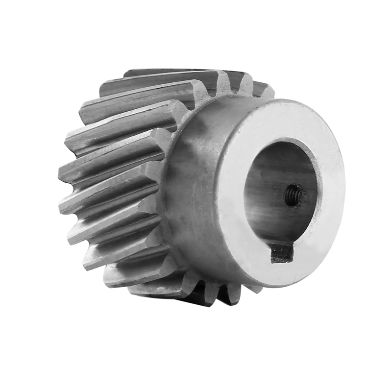
The multiple sizes high precision rack pinion gear system is an essent...
See Details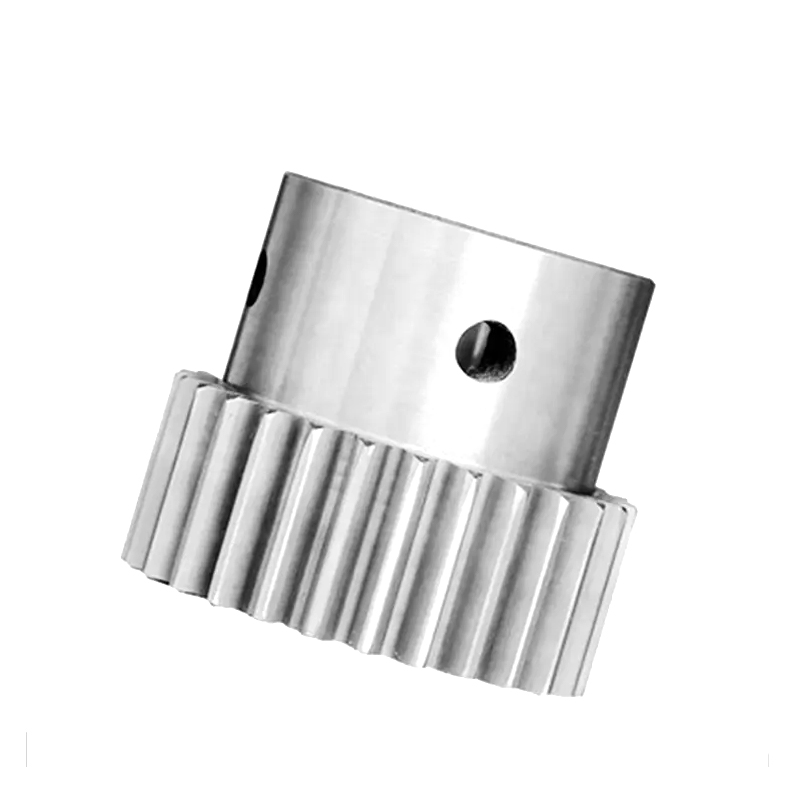
The Stainless Steel Stepped Rack Pinion Gear is a highly versatile and...
See Details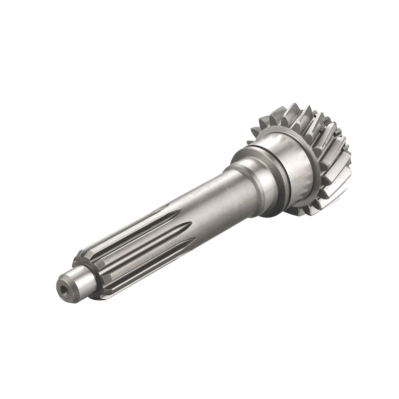
The rust-proof high-precision rack pinion gear is a critical component...
See Details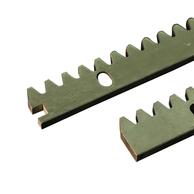
The Metal Steel Gear Rack for Sliding Door Operators is a crucial comp...
See Details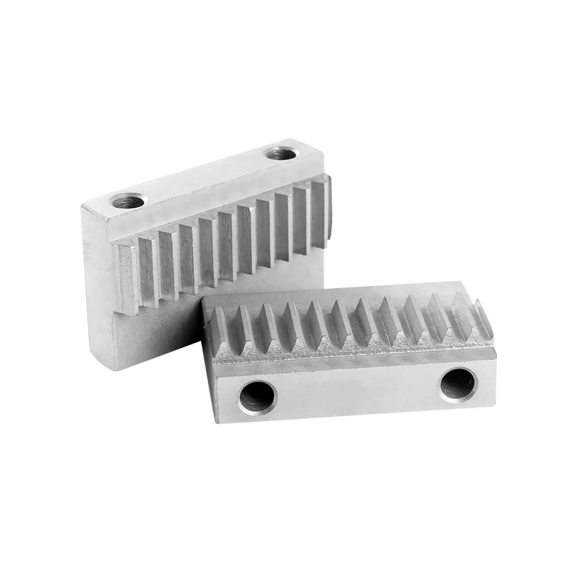
In industrial settings, the performance and longevity of mechanical co...
See Details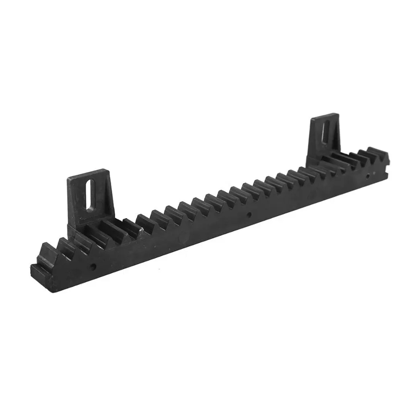
The Two-Hole Track Sliding Door Nylon Gear Rack is a mechanical compon...
See Details
